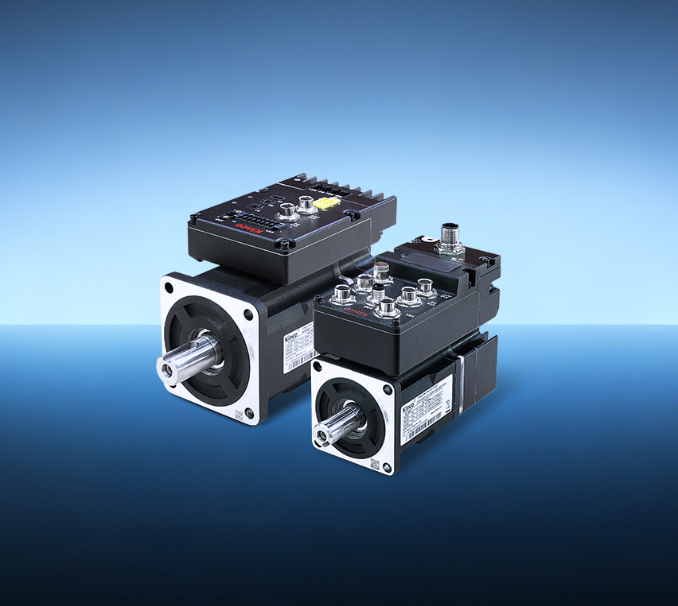
Integrated servo motors combine motor, drive, encoder, and often brake into a single housing. This compact design eliminates separate drive cabinets and long cable runs, but it also introduces constraints that distributed systems do not face.
Kinco‘s brushless DC servo motor in an integrated package can deliver outstanding performance, but only when engineers address the specific factors that limit its capability. The following practices target the most common performance bottlenecks in real-world applications.
Match Inertia Ratio Before Relying on Power Ratings
Selecting a motor by power rating alone is a common starting point, but it frequently leads to suboptimal performance. Two 750 W integrated servo motors from different manufacturers can respond very differently in the same application.
The critical parameter is the inertia ratio between the motor rotor and the driven load. When the load inertia substantially exceeds the rotor inertia, the velocity loop struggles to maintain stability, and settling time at each positioning move increases noticeably.
Calculate the load inertia reflected to the motor shaft before making a selection. For direct-drive applications, this is the load inertia itself; for belt or gear drives, reflect it using the square of the reduction ratio.
Keeping the inertia ratio within the drive manufacturer’s recommended range generally provides a more stable control foundation.
Refine Control Loop Tuning Beyond Auto-Tune
Auto-tuning features on modern drives are convenient. They measure system response and set gain parameters that produce stable operation with minimal effort. The catch is that stability is not the same as optimized performance. Auto-tuning prioritizes safety over responsiveness, typically selecting conservative gains that leave significant margin for improvement.
Manual refinement follows a disciplined sequence. The current loop is best left at manufacturer defaults for most applications. Velocity loop tuning begins by increasing the proportional gain gradually while monitoring oscillation and settling behavior, then backing it off once the system approaches instability.
Add integral gain carefully — enough to eliminate steady-state error, but not so much that overshoot or extended settling time appears. Position loop tuning benefits from feedforward terms. Adding velocity feedforward reduces tracking error during constant-speed motion without increasing overshoot.
Optimize Mounting Stiffness and Thermal Contact
Mechanical installation affects performance far more than many engineers assume. The mounting structure’s stiffness directly influences control loop stability. A flexible bracket or thin mounting plate absorbs torque reaction and introduces compliance that effectively increases the load inertia seen by the motor. This compliance limits how high the velocity loop gains can go before resonance occurs, directly capping system responsiveness.
The same mounting surface serves as the primary heat path. Integrated servo motors rely on conduction through the flange to dissipate heat from both windings and drive electronics.
An uneven or rough surface reduces thermal contact, causing the motor to run hotter under identical loads. Hotter windings increase resistance and reduce torque output. The corrective actions are straightforward: specify a flat, rigid mounting surface machined to the manufacturer’s flatness tolerance, apply thermal interface material if recommended, and torque mounting bolts to the specified value.
These details separate installations that sustain peak performance from those that derate prematurely.
Monitor Internal Thermal Dynamics Proactively
Ambient temperature is only part of the thermal equation. Duty cycle — how frequently the motor accelerates, decelerates, and holds position — determines internal heating more than steady-state operation.
Repeated acceleration cycles generate losses in the windings and switching losses in the drive electronics that accumulate faster than the housing can conduct them away.
Start by calculating the RMS current of the actual motion profile. If the application demands sustained acceleration cycles, the usable continuous torque may differ from the published rating.
Many integrated servo motors include temperature sensors accessible via the communication interface. Monitor these values during commissioning to establish a baseline, then set up alerts for when temperatures approach derating thresholds.
Eliminate External Faults Before Suspecting the Motor
When a servo system loses precision, runs hotter, or develops erratic behavior, the default reaction is often to blame the motor. This assumption frequently wastes time and leads to unnecessary replacements.
External factors produce the same symptoms. Worn couplings introduce backlash that changes load characteristics. Contaminated linear guides or gearboxes add friction that the velocity loop must overcome, effectively changing the load dynamics and requiring different gain settings.
Electrical issues are equally deceptive. Damaged communication cables or loose connectors cause intermittent data loss that manifests as unexpected faults or jittery motion.
Encoder signal degradation can produce position drift without a clear error message. The systematic approach is to isolate the motor from the mechanical load and test its performance independently. Use diagnostic tools to verify encoder signals and communication integrity.
Check that cables are intact, properly shielded, and routed separately from power wiring. Only after ruling out transmission and electrical issues should the brushless DC servo motor itself be considered for service or replacement. This diagnostic discipline reduces downtime and avoids unnecessary component costs.
Maximizing performance from an integrated servo motor is a matter of addressing the real limits — inertia matching, tuning refinement, mounting quality, thermal dynamics, and diagnostic rigor.
The compact, all-in-one design offers significant space and wiring advantages, but those advantages come with specific demands. Apply these practices during commissioning and maintenance, and the system will deliver the responsiveness, precision, and reliability the application requires.
